| Author |
Message |
|
|
I have given up hope of getting TCXO fitted to these devices in the short term....... 
TO overcome this problem i replaced the 32MHz 3.2x2.5mm SMD crystal with a 10ppm part myself:-
Here is a suitable 10ppm 32HMz crystal that can be directly replaced - ideally using a tweezer soldering iron
[url]
https://uk.rs-online.com/web/p/crystal-units/6754920/
[/url]
I have done a straight swap for the above without any other changes and the unit work fine although i have yet had the time to check more reliable communications with BW<62.5KHz
Currently have the following modem settings working ok at 868MHz
Ideally i would like to fit an oscillator module (TCXO) instead of a crystal to get the ppm down to 2ppm and open up the possibility of using the very narrow bandwidths:-
Here is a suitable TCXO but you will need to modify the miniwireless pcb to allow this to work as the current RFM95/98 module are fitted with a SMD crystal and NOT an oscillator!!
[url]
http://www.ebay.co.uk/itm/191830861745
[/url]
To make this mod the output of the TCXO needs to be connected to pin XTA and XTB needs to be open circuit (so a track cut as currently both XTA and XTB are connected to either side of the crystal) The TCXO will need to pick up 3V3 power from somewhere also.
have a look here for the TCXO connection to the SX1276 chip
[url]
www.semtech.com/images/datasheet/sx1276_77_78_79.pdf
[/url]
Hope this helps.
Cheers
Dan
|
 |
|
|
Hi there,
I am using the RFM95W.
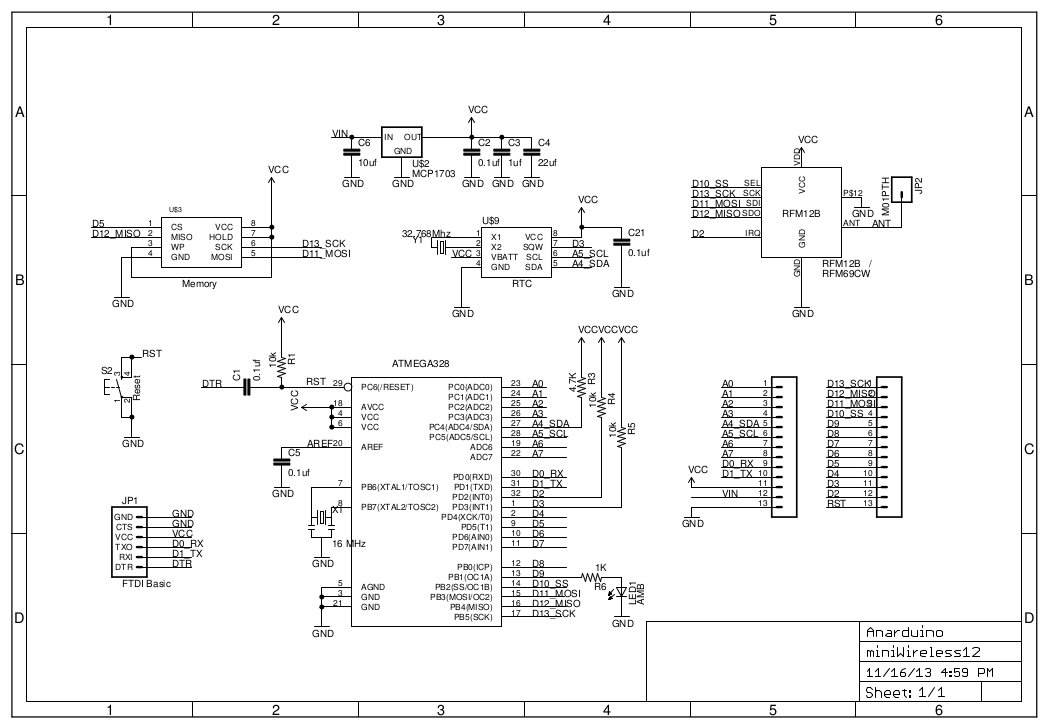
Is there a datailed schematic which shows the how all the pins on the radio module are connected to the Miniwireless carrier board and ultimately to the Atmel 328P chip. The schematic on the web site and the picture below only shows RFM12B and RFM69CW.
In particular what pins from the 328P are connected to the Reset and DIO2 pins on the module
Miniwireless schematic
RFM95 Pinout

Many thanks
Dan
|
|
|
|
Using two RFM95 miniwireless modules (868MHz) I have conducted numerous long range LOS tests.
To date the furthest I have had a two way link reliably communicating was over 20km line of sight. The Arduino code I had running indicated both packet RSSi and background noise floor.
At 20km I still had over 20dB of SNR to hand - with a RSSI of -84dBm!!
this was achieved using the following modem settings and +20dBm TX power:-
For long distances you will need to use narrow bandwidths and high spreading factor - this heavily relies on the relative offset of the 32MHz crystals on each modules. There are ok but by the time they are multiplied up to your TX frequency an unacceptable frequency offset might exist between the TX/RX pair which will mean the carrier will fall outside the receive bandwidth - you may need to play around with the frequency setting for each board to make sure both boards are operating with exaclty (or as close as possible) the same carrier frequency
I also added some code to the RH_RF95.cpp library to output my back ground RSSI as well as my RSSI this allow you to debug your environment and determine if that 4G mobile phone mast is leaking into your receiver.
My experiment location was nowhere near another interferers so my background RSSI was about -97dBm ish
I also used properly grounded coaxial cable feeding a bulkhead Female SMA connector to which a fitted a 3dB whip antenna. the shield of the coax was soldered to an area of the board where i had scrapped of the solder resist to expose the copper ground plane.
http://www.rfsolutions.co.uk/acatalog/info_ANT_8WHIP3H_SMA.html
To optimise the antenna gain I also fine trimmed the length of this antenna so the null in the return loss of the antenna was at exactly 868MHz.
A simple bit of wire is fine for shortish range setups but not really for 3km.
Use this to plan your range experiments:-
http://www.solwise.co.uk/link-budget.htm
In a rural setting I have got about 800m but this was using crude untuned wire antennas at 1m elevation and non optimal modem setting.
Hope this helps.
Regards
Dan
|
|
|
|
I have used on of the Miniwireless modules with the RFM95 radio model installed to transmit packets over a 20km range.
I also ran into issue with loosing packets on narrow bandwidths and higher spreading factor setting.
I suspected the offset in the crystal on each board was causing the down converted IF to fall outside its bandwidth.
I also suspected that there might be some thermal drift in the crystals causing issues also.
I had a look at the 868MHz outputs of each board using a spectrum analyser to work out what offset existed between the two.
I then adjusted the reference oscillator frequency in the library file RH_RF95.h so both modules had exactly the same carrier frequency.
This took a bit of experimentation to get it right.
Im sure a more expensive crystal would allow this board to operate successfully using the lowest bandwidth and highest spreading factors.
Cheers
Dan
|
|
|
|
Using two RFM95 miniwireless modules I have conducted numerous long range LOS tests.
These really are great little boards.
To date the furthest I have had a two way link reliably communicating was over 20km. The Arduino code I had running indicated both packet RSSi and background noise floor.
At 20km I still had over 20dB of SNR to hand - my biggest problem was finding suitable elevated locations but this was much help ed by the use of the following web site.
http://www.solwise.co.uk/link-budget.htm
In a rural setting I have got about 800m but this was using crude untuned wire antennas at 1m elevation and non optimal modem setting.
|
|
|
|